Introduction of Chemical Centrifugal Pump for Filter Press
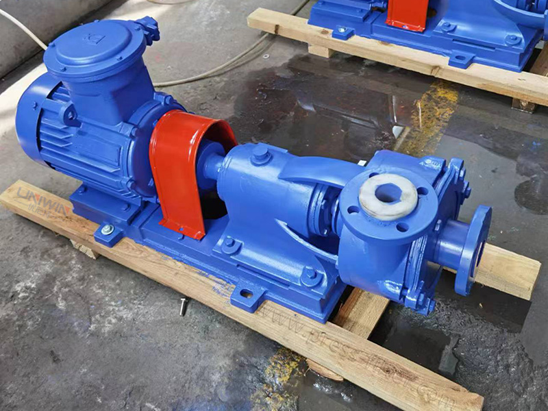
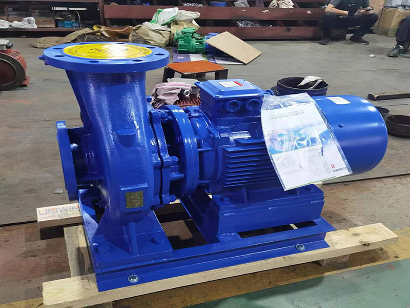
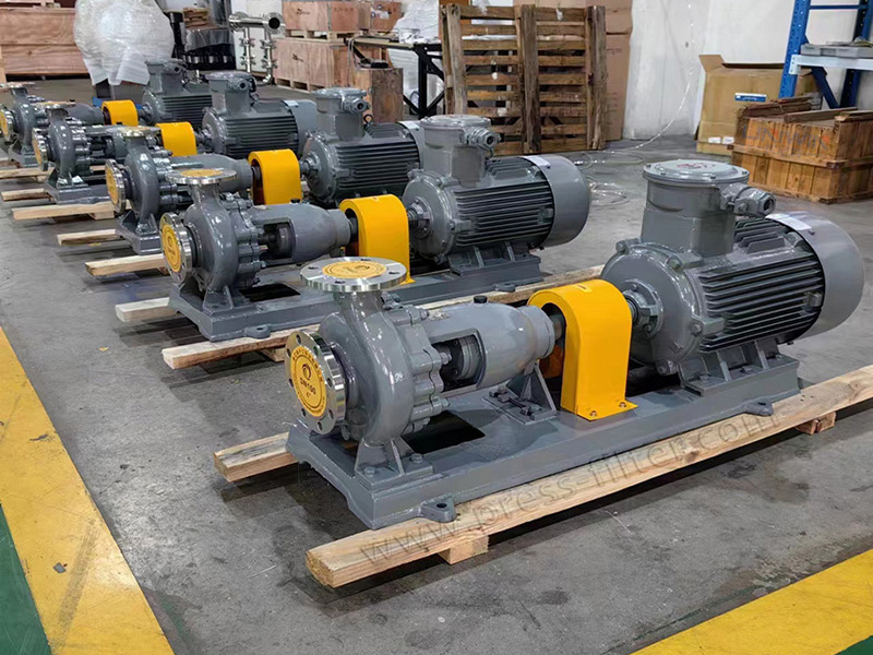
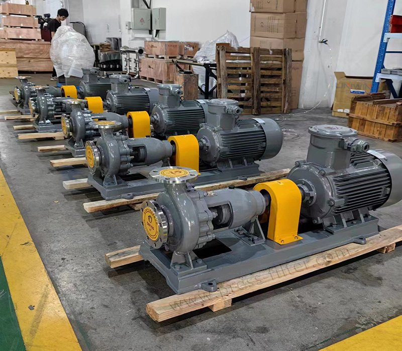
The IH-type stainless steel chemical centrifugal pump, often integrated with filter press systems, is a single-stage, single-suction cantilever design. It’s an energy-efficient alternative to the F-type corrosion-resistant pump. This pump series, ideal for filter press operations, is crafted based on the performance criteria, technical specifications, and testing methods of energy-saving pumps. It’s among the energy-saving pump products endorsed in our country.
Especially in filter press applications, where clean water and other liquids with properties akin to water need to be transferred without solid particles, this pump proves invaluable. It’s extensively used in sectors like urban industrial and agricultural drainage, fire water supply, and for conveying corrosive media at 20°C to 105°C or media with physical and chemical properties similar to water.
Horizontal Stainless Steel Chemical Centrifugal Pump Model Meaning
For example: IH80-65-60A
A: The outer diameter of the impeller is cut for the first time
160: Impeller nominal diameter (mm)
65: Discharge port diameter (mm)
80: Suction port diameter (mm)
IH: International standard chemical centrifugal pump
Product Parameter
| Model | Rotating speed | Flow (m3/h) | Flow(L/S) | Lift(m) | Efficiency(%) | Shaft power(Kw) | Equipped power (Kw) | NPSH (m) | Weight(kg) |
|---|---|---|---|---|---|---|---|---|---|
| IH50-32-125 | 2900 | 12.5 | 3.47 | 20 | 51 | 1.33 | 2.2 | 2 | 45 |
| IH50-32-160 | 12.5 | 3.47 | 32 | 46 | 2.37 | 3 | 2 | 49 | |
| IH50-32-200 | 12.5 | 3.47 | 50 | 39 | 4.36 | 5.5 | 2 | 59 | |
| IH50-32-250 | 12.5 | 3.47 | 80 | 33 | 8.25 | 11 | 2 | 93 | |
| IH65-50-125 | 25 | 1.53 | 2 | 62 | 2.2 | 3 | 2 | 47 | |
| IH65-50-160 | 25 | 2.78 | 32 | 57 | 3.82 | 5.5 | 2 | 53 | |
| IH65-40-200 | 25 | 2.92 | 50 | 52 | 6.55 | 11 | 2 | 63 | |
| IH65-40-250 | 25 | 2.92 | 80 | 46 | 46 | 15 | 2 | 99 | |
| IH65-40-315 | 25 | 3.06 | 125 | 39 | 39 | 30 | 2 | 116 | |
| IH80-65-125 | 50 | 13.9 | 20 | 69 | 3.95 | 5.5 | 3 | 52 | |
| IH80-65-160 | 50 | 13.9 | 32 | 67 | 6.5 | 11 | 2.3 | 57 | |
| IH80-50-200 | 50 | 13.9 | 50 | 63 | 10.8 | 15 | 2.5 | 65 | |
| IH80-50-250 | 50 | 13.9 | 80 | 58 | 18.8 | 30 | 2.5 | 103 | |
| IH80-50-315 | 50 | 13.9 | 125 | 52 | 32.73 | 45 | 2 | 121 | |
| IH100-80-125 | 100 | 27.8 | 20 | 73 | 7.47 | 11 | 4.5 | 57 | |
| IH100-80-160 | 100 | 27.8 | 32 | 73 | 11.9 | 15 | 4.3 | 87 | |
| IH100-65-200 | 100 | 27.8 | 50 | 72 | 18.9 | 30 | 3.9 | 96 | |
| IH100-65-250 | 100 | 27.8 | 80 | 68 | 32 | 45 | 3.6 | 115 |
Please consult us for more models
Filter Press Chemical Centrifugal Pump Features
The IH-type stainless steel chemical centrifugal pump boasts a logical design and dependable hydraulic performance. It’s compact, lightweight, and offers excellent resistance to cavitation, consuming minimal power. This pump is user-friendly, easy to maintain, and operates efficiently. The IH single-stage, single-suction centrifugal pump features a horizontal design, aligning well with the needs of most pipeline installations.
Conditions of Use
The IH stainless steel chemical pump has a maximum operational pressure of 1.6 MPa. The medium’s temperature must not exceed 80℃. If required, a dual-end seal cooling mechanism can be utilized, allowing for the transportation of mediums with temperatures ranging from 20°C to +280°C.
Note: Users can choose different materials for the main parts of the flow-passing part of the pump according to the corrosiveness of the medium being transported.
Installation Dimension Drawing
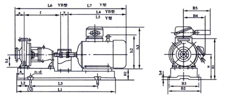
| Model | Motor model power(Kw) | Shape and installation dimensions | ||||||||||||||||||
|---|---|---|---|---|---|---|---|---|---|---|---|---|---|---|---|---|---|---|---|---|
| A | L1 | L2 | L3 | L4 | a | f | X | L5 | B2 | B3 | B4/B5 | h1 | h2/h2' | h3 | H | H1 | H2 | n-d | ||
| IH50-32-125 | YB801-4/0.55 | 820 | 150 | 540 | 330 | 80 | 385 | 100 | 895 | 360 | 320 | 150/225 | 112 | 170/325 | 25 | 197 | 317 | 442 | 4-φ19 | |
| YB802-2/1.1 | ||||||||||||||||||||
| YB90S-2/1.5 | 80 | 360 | 925 | 155/225 | 190/340 | |||||||||||||||
| IH65-50-125 | YB801-4/0.55 | 80 | 820 | 150 | 540 | 330 | 80 | 385 | 100 | 895 | 360 | 320 | 150/225 | 112 | 170/325 | 25 | 197 | 337 | 442 | 4-φ19 |
| YB802-4/0.75 | ||||||||||||||||||||
| YB90L-2/2.2 | 920 | 170 | 600 | 385 | 950 | 390 | 350 | 155/225 | 190/340 | 30 | 447 | |||||||||
| IH65-40-200 | YB802-4/0.75 | 80 | 920 | 170 | 600 | 330 | 100 | 385 | 100 | 915 | 390 | 350 | 150/225 | 160 | 170/325 | 30 | 245 | 425 | 490 | 4-φ19 |
| YB90S-4/1.1 | 360 | 945 | 155/225 | 190/340 | 495 | |||||||||||||||
| YB90L-4/1.5 | 385 | 970 | ||||||||||||||||||
Installation Order
1. Position the unit on the foundation using embedded anchor bolts. For alignment, insert wedge pads between the base and the foundation.
2. Detach the coupling. Position a level on the pump shaft or base as needed. Adjust the leveling pad to ensure the unit is level, then secure the anchor bolts to prevent any shifts.
3. Fill the base and anchor bolt inspection holes with concrete.
4. Once the concrete has been set, tighten the anchor bolts and re-examine the pump shaft for smooth operation.
5. After attaching the pipeline and confirming the prime mover’s rotation direction, reconnect the coupling. Reassess the shaft’s concentricity and measure the top and bottom of the coupling’s outer circle. The discrepancy between the left and right should not surpass 0.1mm. For the end face gap, the largest and smallest gap difference within a week shouldn’t exceed 0.3mm.
6. After the unit has run for 3 to 4 hours, perform a final check. If no issues arise, the installation is considered successful.